ok with some help of the Arduino forums and references, this is the current code which works almost 100%
Code:
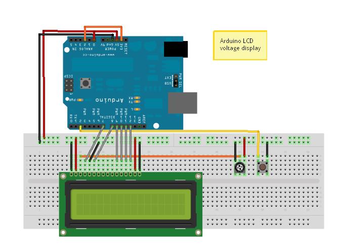
/*Arduino Controlled Voltage Monitor
Code by Will Lyon 12/5/2010
Code for project Power House on TBCS
http://www.thebestcasescenario.com*/

#include <LiquidCrystal.h>

//Initialize the library with the numbers of the interface pins
LiquidCrystal lcd(7, 8, 9, 10, 11, 12);

void setup()
{
  lcd.begin(16, 2);                      //Set up the LCD's number of columns and rows
  lcd.print("  POWER  HOUSE");           //First line opening message
  lcd.setCursor(0, 1);
  lcd.print("Desktop Pwr Unit");         //Second line opening message
  delay(5000);
  lcd.setCursor(0, 1);                   //Clear bottom line
  lcd.print("                ");
  lcd.setCursor(0,0);
  lcd.print(" 3v    5v   12v");          //Update top line readout
}

void loop()
{
  lcd.setCursor(0, 1);
  float f = analogRead(0) * 4.9 / 1023;     // 3.3 => 9.9
  lcd.print(f, 2);  // print float with one decimal

  lcd.setCursor(6, 1);
  f = analogRead(1) * 5.0 / 1023;         // 5.0 => 9.9
  lcd.print(f, 2);


  lcd.setCursor(11, 1);
  f = analogRead(2) * 12.0 / 1023;         // 12.0 => 25.0
  lcd.print(f, 2);

  delay(1000);
}
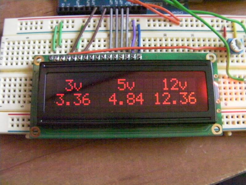
I need to find out why the 5v and 12v aren't reading properly. they're just sitting at 5.00 and 12.00 and don't change. if I change the coding (in the analogRead() ) sections for those two inputs, the value on the screen changes to whatever the multiplier is 
the 3v line I had to set the multiplier to 4.9 so the display readout was the same as what my multimeter said the line has. as for the other two, my meter says 4.85b and 12.4v respectively., and the lcd says 5.00 and 12.00
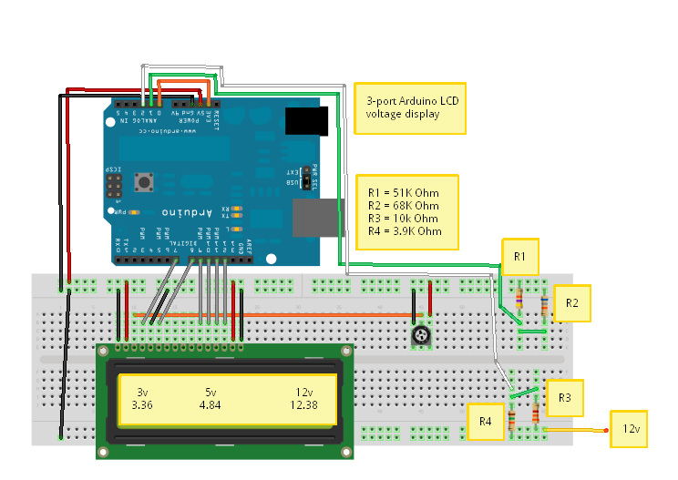
I'm also using a voltage divider on the 12v line so as to not fry the Arduino. Here's how that is set up:
12v---|51K|---+---|68K|---GND
The Arduino's analog pin is connected to the "+"
With this the sense pin is seeing 5.40v. Should I put a 10K to ground off the two analog pins for 5v and 12v?


 Reply With Quote