
Originally Posted by
Oneslowz28

How big is your code? You could run this on a $4 Atmega 8 if its not too big.
here's the code, and I'm running it on a $4 Atmega 328 lol  the smaller chip might be useful for space/trace routing reasons, and I've got a serial IC programmer, but the only programming I know is Arduino, so I'd have no idea how to transfer the coding
Code:
// Controlling a servo position using a temperature sensor
// by Michal Rinott <http://people.interaction-ivrea.it/m.rinott>
// edited 5-12-2010 by Will Lyon to include base setting for servo if voltage not detected on pin 7
// edited again 7-4-2010 by crenn to simplify the code a little
// edited yet again 7-5-2010 by crenn to add features
// edited again 7-21-2010 by Will Lyon - recalibrated servo positions
// edited again 10-15-2010 by crenn - slow down servo when computer is off
// edited again 10-15-2010 by Will Lyon, with new VarSpeedServo library to slow servo movement
// VarSpeedServo library from Korman on Arduino.cc forums

#include <VarSpeedServo.h>

VarSpeedServo myservo;                      // create variable speed servo object to control a servo

//Constants
const unsigned char CONTROL = 5;            // digital pin used to detect if the system is on or off
const unsigned char TEMP_SENSOR = 0;        // analog pin used to connect the temp sensor
const unsigned char MAX_SAMPLES = 10;       // number of temp sensor samples to average
const unsigned char OFF_POSITION = 180;     // position of servo when no voltage is detected on pin 5
const unsigned char LOW_POSITION = 160;     // servo position for lowest temp
const unsigned char HIGH_POSITION = 135;    // servo position for highest temp

//Main global varibles
char trigger = 0;                           // varible used to store the control pin value
unsigned int val = OFF_POSITION;            // variable to read the value from the analog pin

unsigned int updateAvgtemp(){
  static int history[MAX_SAMPLES]={0};
  static unsigned char lastHist=0;
  static unsigned char numHist=0;
  unsigned int temp=0;
  unsigned char counter=0;
  unsigned char arcount=0;
  history[lastHist] = analogRead(TEMP_SENSOR);
  if(numHist<MAX_SAMPLES)
    ++numHist;
  arcount=lastHist;
  ++lastHist;
  if(lastHist>=MAX_SAMPLES)
    lastHist=0;
  temp=0;
  counter=0;
  do{
    temp+=history[arcount];
    arcount--;
    if(arcount>MAX_SAMPLES)
      arcount=(MAX_SAMPLES-1);
    counter++;
  }while(counter < numHist);
  return (temp/numHist);
}

void setup()
{
  pinMode (CONTROL, INPUT);                                // sets the control pin to input
  myservo.attach(9, HIGH_POSITION, LOW_POSITION);          // attaches the servo on pin 9 to the servo object
  digitalWrite(CONTROL, LOW);                              // ensure internal pullup resistor is disabled.
}
void loop()
{
  trigger = digitalRead(CONTROL);                          // read input of pin CONTROL  and store it
  if (trigger == HIGH){                                       // reads if pin CONTROL, if true, do this:
    val = updateAvgtemp();                                 // read the value of the temp sensor (value with range of 1024)
    val = map(val, 350, 700, LOW_POSITION, HIGH_POSITION); // scale it to use it with the servo (value between 160 and 120)
    myservo.slowmove(val, 0);                              // sets the servo position according to the scaled value
  }
  else {
    while(val<OFF_POSITION){
      val++;
      myservo.slowmove(val, 0);
      delay(100);
    }
    myservo.slowmove(OFF_POSITION, 1);         // sets servo position to 180 if above statment is false, at slowest speed
  }
  delay(125);                                  // wait 25ms for the servo to move to it's new position and also 100ms until it gets the new value
}
Originally Posted by
NightrainSrt4
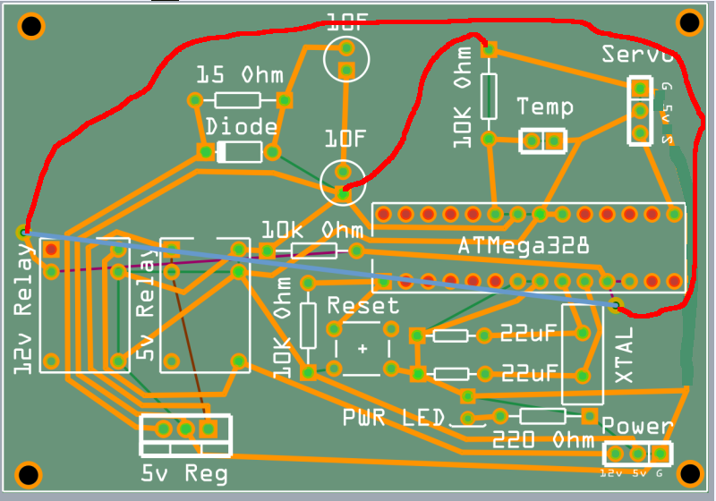
It looks pretty good to me, at least coming from a graph theory point of view. You could probably write an algorithm using incidence lists to draw/approximate possible graphs, or pcb layouts in your case. But aside from testing for planarity, which yours essentially is, the only other thing I could think of is to use a take on the shortest path problem to design a layout that used the minimal amount of pcb trace while still creating a planar graph.
Sorry, going all CS/Math on you. Been stuck designing algorithms for this type of stuff all year, and the last few weeks we've had a focus on graphs.
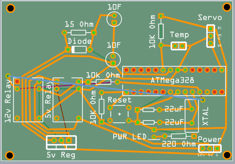
Looks good to me as it is. With a small design like this it tends to be more about the visuals and getting everything onto the pcb size that you want than to minimize trace material,etc. Looks good.
Yea I basically tried to fit it all in in as little space as possible. The reason for the empty space @ top left is that the two 10F caps are going to lay flat in that space, so it works out nicely. That's also why the diode and resistor are in the center, so the caps come down to either side


 Reply With Quote


 anyone have any ideas?
