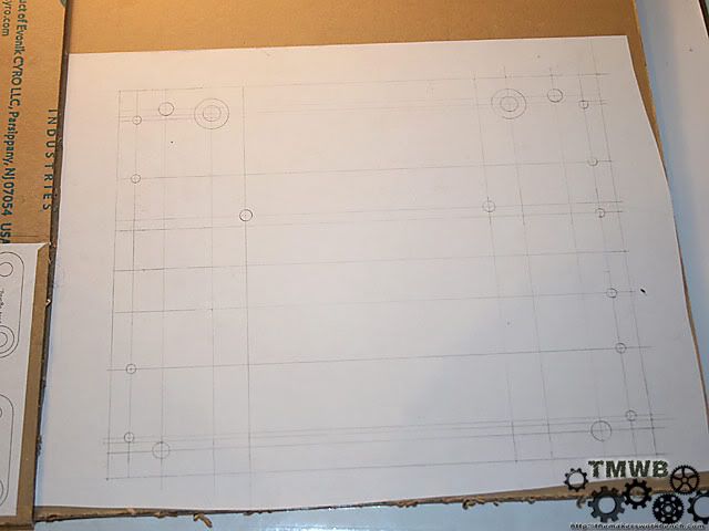
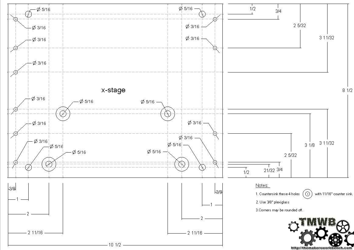
Just finished the technical drawing for the X - Stage. Here is a scaled down image so you guys can see what I am doing.


Just finished the technical drawing for the X - Stage. Here is a scaled down image so you guys can see what I am doing.
Charles (CJ) Gantt: Coil Gun // Biohazard // Circuits // 3D Printer // CoD MW2 Case // TBCS 4GHz Club
Sites: The Makers WorkBench // CJ Gantt Photography

Those are some pretty complex drawings you got going on, wish I could do something of that level.
Looking good as always and with everything you do. Keep up the good work mate!
It's like JFK announcing the moon mission. He had no expertise in space travel, and no way of knowing if it would work. He just announced "we're going to the moon" and then they made it happen because everyone was on the same page and working towards the same goal. If he had said "well, let's get some people in space, and we'll see how far out we can get, and if I find someone to make a rocket strong enough, we could possibly approach the moon's orbit and maybe land" it wouldn't have happened.
Ever had one of those nights where you could not sleep because you wanted to work on something. Tonight was one of those nights. I went ahead and cut out the new x stage and assembled it. It fits perfectly and moves smooth as butter. I will post pics tomorrow.
Charles (CJ) Gantt: Coil Gun // Biohazard // Circuits // 3D Printer // CoD MW2 Case // TBCS 4GHz Club
Sites: The Makers WorkBench // CJ Gantt Photography

Mmmmm technical drawings.... Good job so far, keep it up!
-CollinstheClown
Update time:
So I got a little restless last night and could not sleep. So what better to do than work on the McWire. I cut the new X stage plexi out and assembled all if the parts.
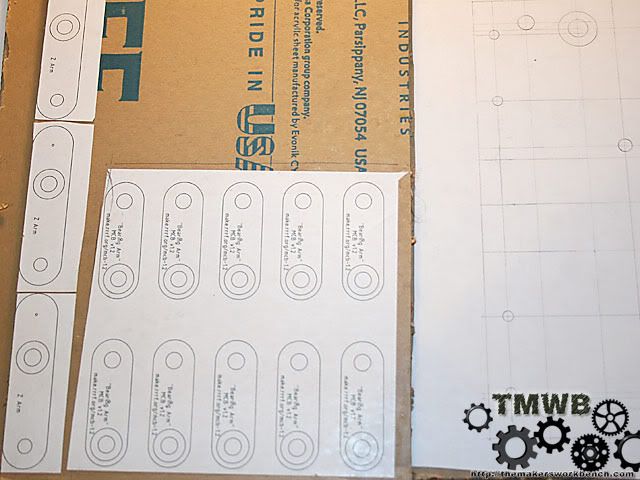
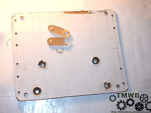
The first thing I had to do was glue the hand drawn X stage to the plexi. An Elmers glue stick make quick work of this. I used a ruler to smooth out any bumps and ripples.
Did the same with the bearing arms
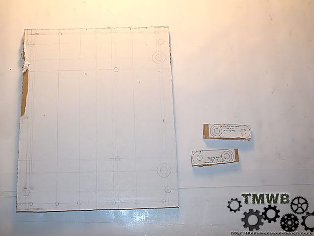
Then I had to cut them out.
My jigsaw is a little old and the cuts were a little rough. Nothing a little sanding on the drum sander wouldn't fix. I pre-drilled all the holes.
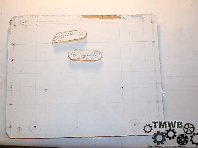
Then counter sunk the 4 holes that required it.
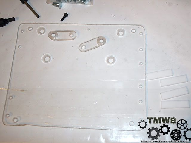
Removed the protective paper and everything looks great.
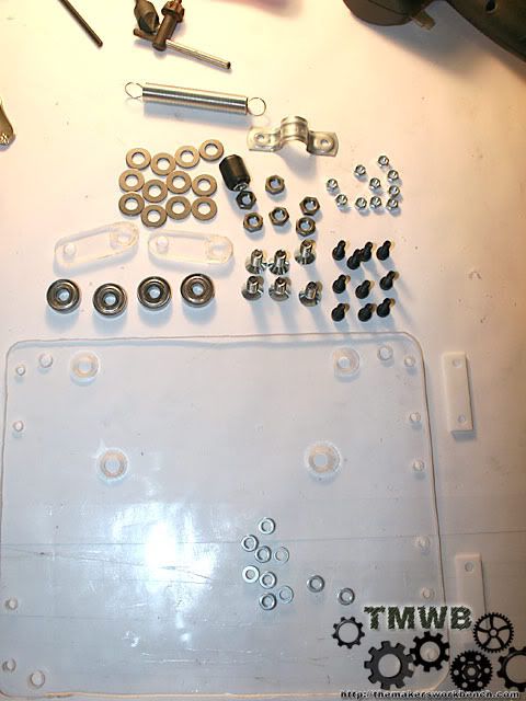
Now I laid out all of the hardware and parts I needed to assemble the X stage.
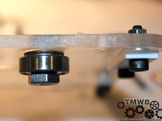
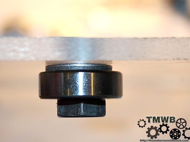
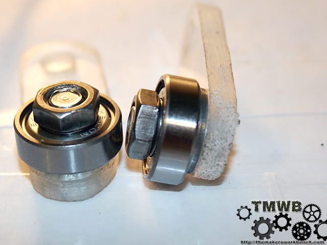
Next I attached the PTFE slide bearings and the Skate bearings that go on the outside of the front rail.
The next step is to attach the remaining 2 bearings to the bearing arms. The order goes like this. 5/16 flat head screw>bearing arm> 5/16" flat washer>skate bearing>hex nut.
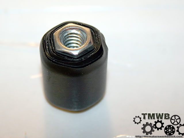
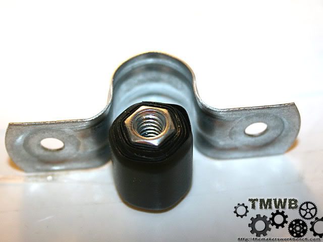
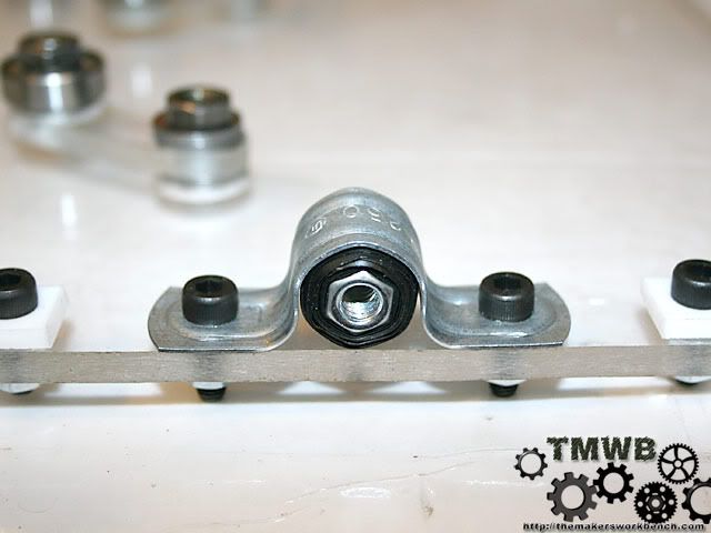
Now lets build the captive nut. This is the nut that will convert the radial motion of the lead screw and convert it into linear motion. You need a 1/4 - 20 coupling nut and a roll of electrical tape. Wrap the nut with the tape until it is thick enough that it just fits inside of the conduit support. You want it to be just snug. Not so bulky that it has to be forced to fit.
Now lets finish assembling the x stage. Install the bearing arms onto the bottom of the plexi using 5/16 machine screws. Place a 5/16 washer between the bearing arm and x stage plexi. Then slide on the bearing arm. Add another washer then a hex nut. Repeat for the next side. Then bolt on the captive nut using the same M5 cap screws that you used for the PTFE bearings.
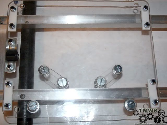
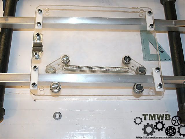
Now put it on the rails and make sure everything fits.
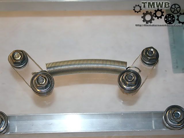
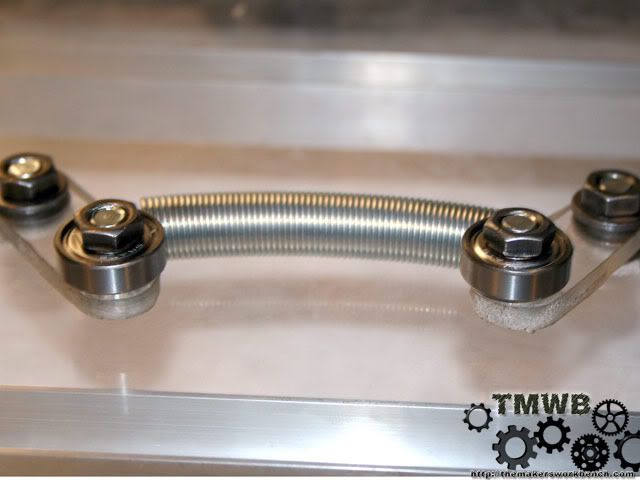
Now we need to add some tension to hold the bearings on the bearing arms firm against the rail. A 4" 5lb extension spring will work nicely. I drilled a 3/16" hole in the middle of the bearing arms and bent the spring ends so I could slide them though the holes. Then I bent them back flat with the bearing arms. The excess spring loop is tucked inside the spring.
Now I am off to build the Y stage.
Charles (CJ) Gantt: Coil Gun // Biohazard // Circuits // 3D Printer // CoD MW2 Case // TBCS 4GHz Club
Sites: The Makers WorkBench // CJ Gantt Photography
This reminds me alot of the easy mill, but a bit more pro. Not to mention its a printer.
-CollinstheClown
The main design is a previous design for a Desktop CNC router by Tom McWire. He posted the design under the GPL and the RepRap core team modified and improved upon the design to make it more precise and stable. The only real major difference is the print head will be bolted to the z stage instead of a dremel. I have been thinking of putting together a parts kit that will include everything but the stepper motors and the electronics.
Charles (CJ) Gantt: Coil Gun // Biohazard // Circuits // 3D Printer // CoD MW2 Case // TBCS 4GHz Club
Sites: The Makers WorkBench // CJ Gantt Photography


nice work! lookin good. +rep for the work on the drawings!
Arctic Cat * Maximum Security * Cribbage Board * Rockin Case * Armor Redux
Tempest SXR * Power House * Red Comet * ICHIWZ * Acrylic Headphone Hook
Continuing sponsorship support from PCBoard.ca
Thanks for the rep. On a side note does anyone know of a good source for solder paste in a syringe.
Charles (CJ) Gantt: Coil Gun // Biohazard // Circuits // 3D Printer // CoD MW2 Case // TBCS 4GHz Club
Sites: The Makers WorkBench // CJ Gantt Photography

Looking good... Any idea what your maximum travel distances are for this? all directions?
 Posting Permissions

 Reply With Quote